


Pine fun - Display
Having switched the development workflow from the Pine-A64-LTS board to the real deal - the PinePhone - in the previous article, it is time to turn our attention to the arguably most challenging parts of the hardware, namely the display subsystem.
Why do I regard this part as the most challenging? The display subsystem of a mobile device is not solely one peripheral but a conglomerate of several devices that are (more or less) under software control and need to work together. The complexity of the interplay and domain-specific terminology can be quite staggering. MIPI, DSI, PLL, PHY, panel, plane, channel, connector, encoder, regulator, mixer, CRTC, RSB, TCON, LVDS, PWM. Are you still with me?
A little Reset life hack
As if the cryptic terminology does not make one feel miserable enough, we will have to make ourselves comfortable with the idea to reset and boot our test hardware many hundreds of times. To keep up our morale, we should remove all obstacles that could possibly bother us while iterating.
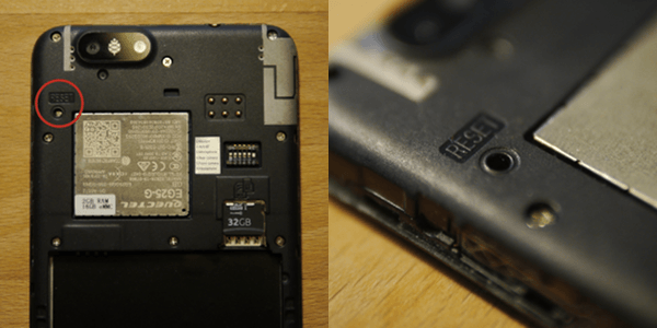
The PinePhone is equipped with a reset button, which is a nice feature. It is normally hidden behind the back cover and is meant to be operated with a paper clip.
|
|
There is tiny button inside the hole.
|
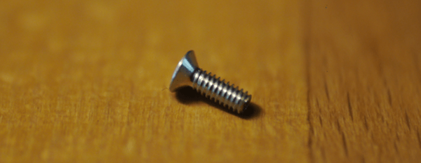
For the purpose of developing a display driver, the button location is rather inconvenient though. For each test cycle, on would need to pick up a bent paperclip, press the button using the paperclip, turn the phone around to see what happens on the display, and put it back resting on the display to reach the reset button again. Imagining myself fiddling with a paperclip and turning around the phone hundreds of times, there had to be a better solution. Looking around for inspiration, my eyes met this little guy.
|
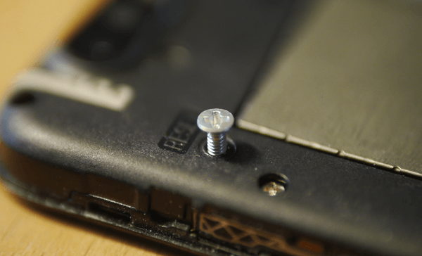
Wouldn't this make a nice user interface for the button hole? Sure enough! It fits snugly in the hole while still being able to move like a proper button should.
|
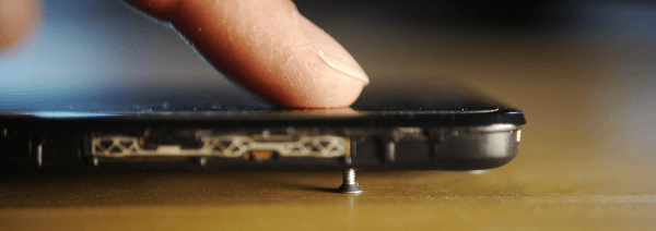
After carefully turning around the phone with the lose screw inserted, the entire phone has magically turned into one giant reset button. Even better, the tactility of pressing the button is rather satisfying.
|
I can hardly stop myself resetting the phone now. It's those little things that can make one's life so much better.
Driving the display with a bare-bones Linux kernel
Not knowing much about the internal structure of the display hardware, it is good to take Linux as a working starting point. When booting Armbian Linux, the display works after all. Observing the Linux boot, the following messages seem obviously be related to the display.
 [    5.936404] Console: switching to colour frame buffer device 170x48
 [    5.955920] simple-framebuffer be000000.framebuffer: fb0: simplefb registered!
 [    5.959687] mmc1: new SDHC card at address 0001
 [    5.967848] sun4i-drm display-engine: bound 1100000.mixer (ops 0xffff800010e340c0)
 [    5.979490] sun4i-drm display-engine: bound 1200000.mixer (ops 0xffff800010e340c0)
 [    5.990232] sun4i-drm display-engine: No panel or bridge found... RGB output disabled
 [    6.000377] sun4i-drm display-engine: bound 1c0c000.lcd-controller (ops 0xffff800010e2f8d0)
 [    6.012100] sun4i-drm display-engine: bound 1c0d000.lcd-controller (ops 0xffff800010e2f8d0)
 [    6.026726] sun8i-dw-hdmi 1ee0000.hdmi: Detected HDMI TX controller v1.32a with HDCP (sun8i_dw_hdmi_phy)
 [    6.117391] sun8i-dw-hdmi 1ee0000.hdmi: registered DesignWare HDMI I2C bus driver
 [    6.130875] sun4i-drm display-engine: bound 1ee0000.hdmi (ops 0xffff800010e333f8)
 [    6.200146] fb0: switching to sun4i-drm-fb from simple
 [    6.210896] Console: switching to colour dummy device 80x25
 [    6.216994] [drm] Initialized sun4i-drm 1.0.0 20150629 for display-engine on minor 0
 [    6.603061] Console: switching to colour frame buffer device 170x48
 [    6.641668] sun4i-drm display-engine: [drm] fb0: sun4i-drmdrmfb frame buffer device
Correlating those words with the device tree brings us to the device node of the so-called display engine.
  de: display-engine {
   compatible = "allwinner,sun50i-a64-display-engine";
   allwinner,pipelines = <&mixer0>, <&mixer1>;
   status = "disabled";
  };
The device node's compatible string, in turn, draws the connection to the part of the Linux kernel that is of interest to us.
 linux$ grep -r "allwinner,sun50i-a64-display-engine"
 drivers/gpu/drm/sun4i/sun4i_drv.c: { .compatible = "allwinner,sun50i-a64-display-engine" },
So drivers/gpu/drm/sun4i/ seems to be good starting point for exploration.
Having identified the driver code that want to execute for sure, we have to answer two questions:
-
What are the in-kernel dependencies of this driver code? All those dependencies are of interest to us because they are prerequisites.
-
Which parts of the Linux kernel are unrelated to the driver functionality? We would like to drop those parts to narrow our view on the interesting driver code as much as possible.
The investigation of those two questions is an iterative process that follows the pattern discussed previously. In our present case, the success criterion of our custom-built bare-bones Linux kernel is the display of the little Tux at the top of the screen. Our kernel won't need anything else, Tux is enough.
To find the smallest possible selection of kernel configuration parameters, the bisecting approach that we previously used for isolating the network driver becomes handy again. Without further ado, here comes the solution as supplement for our target.inc.
 # framebuffer driver
 LX_ENABLE += DRM DRM_SUN4I DRM_SUN8I_MIXER DRM_SUN8I_DW_HDMI

 # determined by bisecting kernel configuration options (needed by fb driver)
 LX_ENABLE += CMA DMA_CMA MFD_AXP20X_RSB REGULATOR REGULATOR_AXP20X
 LX_ENABLE += PROC_FS SYSFS

 # to automatically set up screen mode at boot time
 LX_ENABLE += FRAMEBUFFER_CONSOLE

 # show Tux
 LX_ENABLE += LOGO
Don't ask how often I operated the reset button to find this global minimum of kernel configuration parameters.
With the bare-bones Linux kernel running, we can use Busybox to interactively poke around with the driver. It is nice to see some response, like the display going dark.
 / # mkdir proc
 / # mkdir sys
 / # mount -tproc proc
 / # mount -tsysfs sys
 / # cd /sys/devices/platform/display-engine/graphics
 /sys/devices/platform/display-engine/graphics # cd fb0/
 /sys/devices/platform/display-engine/graphics/fb0 # echo 1 > blank
 /sys/devices/platform/display-engine/graphics/fb0 # echo 0 > blank
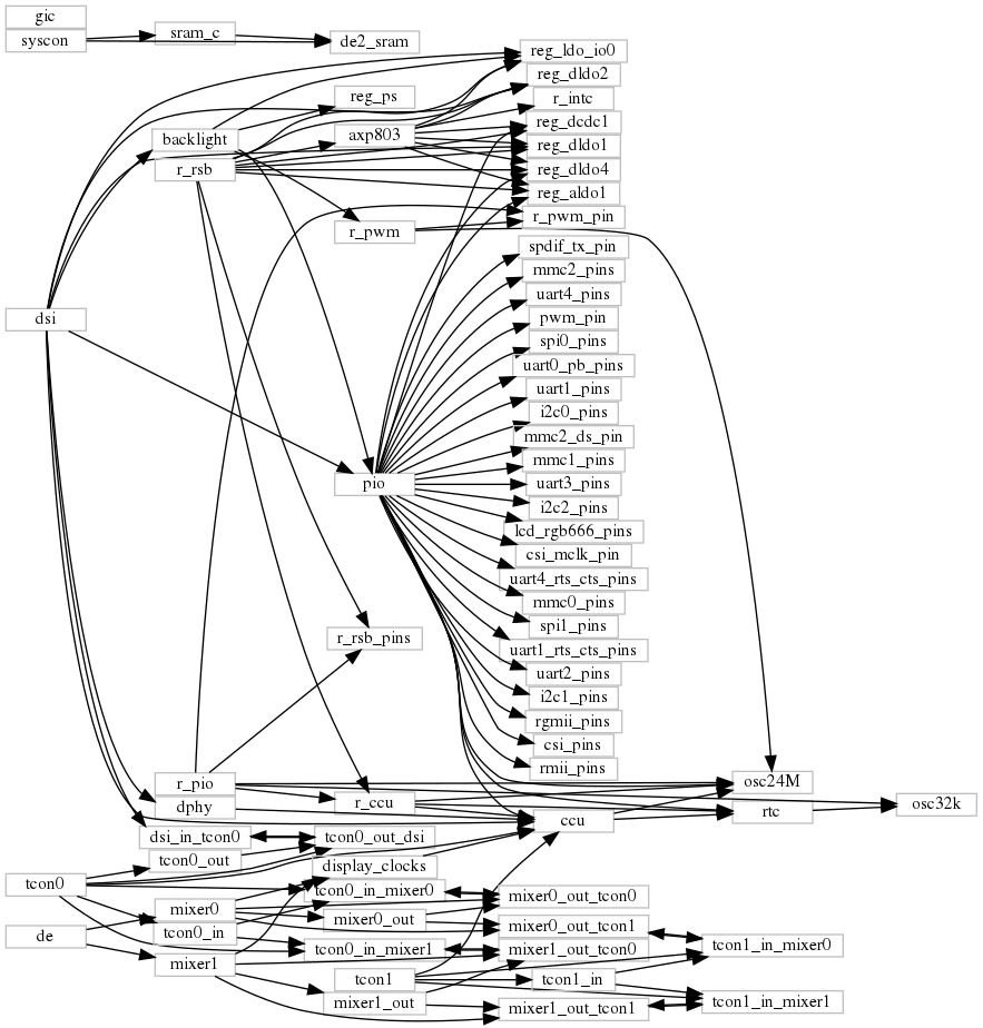
To further tighten our focus, the next step is the pruning of the device tree using the DTS-extract tool discussed earlier. For reference, the device tree extracted with following arguments suffices to allow Linux to drive the display. The central element is the Allwinner Display Engine (DE).
 genode$ ./tool/dts/extract --select /backlight --select de --select dsi \
                            flat_pinephone.dts
The resulting device-tree nodes at a glance:
|
|
Device-tree nodes related to the display engine and the DSI output.
|
Let's not get scared. A glossary of the terminology seen the picture should lift the clouds a bit.
-
The PIO device controls general-purpose I/O pins. We explored this device previously. All pins are naturally related to the PIO controller but only a few of them are actually relevant for the display. So we can consider the large number of pin nodes as just noise for the most part.
-
All nodes prefixed with r_ belong to a certain part of the SoC that is referred to as "RTC" (real-time clock). Those parts are powered independently from the ARM application processor and are meant to be driven by a small microcontroller called AR100 that ought to manage power.
-
The r_rsb controller is a two-wire bus similar to I2C that connects the A64 SoC with a separate power management chip (PMIC, or AXP803). This chip is responsible for generating various voltages on the board. For driving the display, this chip is important because it provides the power for the LCD display part, which is off by default. So in order to power the display, the driver needs to talk via the RSB bus to the PMIC chip.
-
TCON0 and TCON1 are two interfaces of the SoC where a display can be connected. So the SoC supports dual-head scenarios like driving an HDMI display and an LCD display at the same time.
-
CCU stands for central clock unit. It controls the configuration and gating of all kinds of internal clocks and reset lines. The R_CCU refers to the clocks and reset lines associated with the RTC part of the chip.
-
The backlight is a separate device. Its brightness is controlled via pulse-width-modulated digital signal generated by the r_pwm device.
-
The DPHY is responsible for the physical link of the digital connector. Electronics stuff.
-
All these mixer nodes are related to the display engines ability to blend multiple images together.
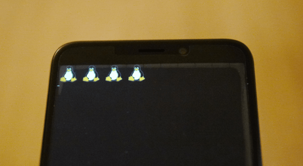
When booting our bare-bones Linux kernel with the pruned device tree, Tux shows up, and the last life signs of the kernel are the following messages.
 sun4i-drm display-engine: No panel or bridge found... RGB output disabled
 sun4i-drm display-engine: bound 1c0c000.lcd-controller (ops 0xffffffc010272138)
 sun4i-drm display-engine: bound 1c0d000.lcd-controller (ops 0xffffffc010272138)
 sun4i-drm display-engine: bound 1ca0000.dsi (ops 0xffffffc010275810)
 [drm] Initialized sun4i-drm 1.0.0 20150629 for display-engine on minor 0
 sun4i-drm display-engine: [drm] Cannot find any crtc or sizes
 Console: switching to colour frame buffer device 90x90
 sun4i-drm display-engine: [drm] fb0: sun4i-drmdrmfb frame buffer device
 sun6i-mipi-dsi 1ca0000.dsi: Attached device xbd599
 panel-sitronix-st7703 1ca0000.dsi.0: 720x1440@55 24bpp dsi 4dl - ready
|
|
Hello my friends, nice to see you!
|
The logo. That's all we want from the Linux kernel for now.
A monolithic display driver running on Genode
In the networking article we covered the path from a down-stripped bare-bones Linux kernel to a Genode driver component using Genode's device-driver environment.
The same principle method works equally well for transplanting the display driver,
-
Selecting the relevant driver sources,
-
Generating dummy implementations using the tool/dde_linux/create_dummies tool,
-
Taking cues from the existing DDE-Linux-based drivers for supplementing custom Linux emulation code,
-
Using a custom run script (appropriately named framebuffer_pinephone.run) as a dedicated test bed for the driver,
-
Resolving the access to device resources like memory-mapped I/O ranges and interrupts by enhancing the platform-driver configuration step by step.
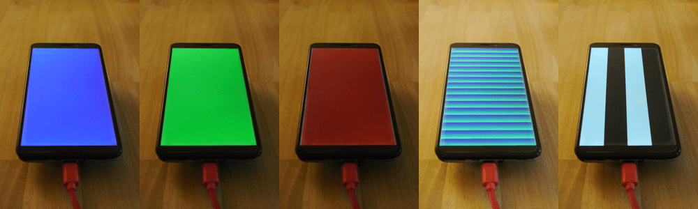
For the test bed, the framebuffer test is a handy tool. When combined with a display driver, it presents a sequence of colors and patterns, and it nicely highlights the border of the screen to verify the entirety of the framebuffer is indeed visible.
|
|
The _framebuffer_pinephone.run_ scenario.
|
In the test scenario, the test-framebuffer component takes the place of the GUI server, providing a capture service. The framebuffer driver plays the role of a mere capture client that captures the synthetic pixel data generated by the test-framebuffer component.
For interfacing the Linux kernel code with Genode's capture session interface, the driver uses the following kernel function declared in linux/fb.h as a hook to get hold of the pixel data.
int register_framebuffer(struct fb_info *fb_info);
This is arguably quite primitive and does not allow the use of many driver features. However, we have to start somewhere.
The framebuffer driver interacts with device hardware through the platform driver as introduced earlier. The following picture shows all the devices the driver interacts with.
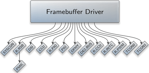
|
This octopus-resembling creature raises two tricky questions.
-
Is it reasonable to entrust the driver with the access to all those devices? Given the complexity of the ported driver code, this seems risky, doesn't it?
-
Some of the devices seem to be relevant to other drivers, too. If we grant the framebuffer driver exclusive access to those devices, how can we combine the framebuffer driver with other drivers running on the same system?
We will come to solving those questions soon. For now, let's enjoy the colorful display for a bit.
For reference, the entire commit for the monolithic framebuffer driver can be found here.