


Zynq guide #2 - enabling the programmable logic
After the basic board-enablement covered by the first article of this series, it’s eventually time to focus on the distinct feature of the Zynq-SoC - the FPGA aka programmable logic (PL).
As we saw in the last article, booting up a Zynq-based board with Genode is pretty much the same as on any other platform. In fact, I don’t find the serial output very thrilling given that it originates from a piece of hardware lying on my desk which features many, more exciting yet untouched, peripherals.
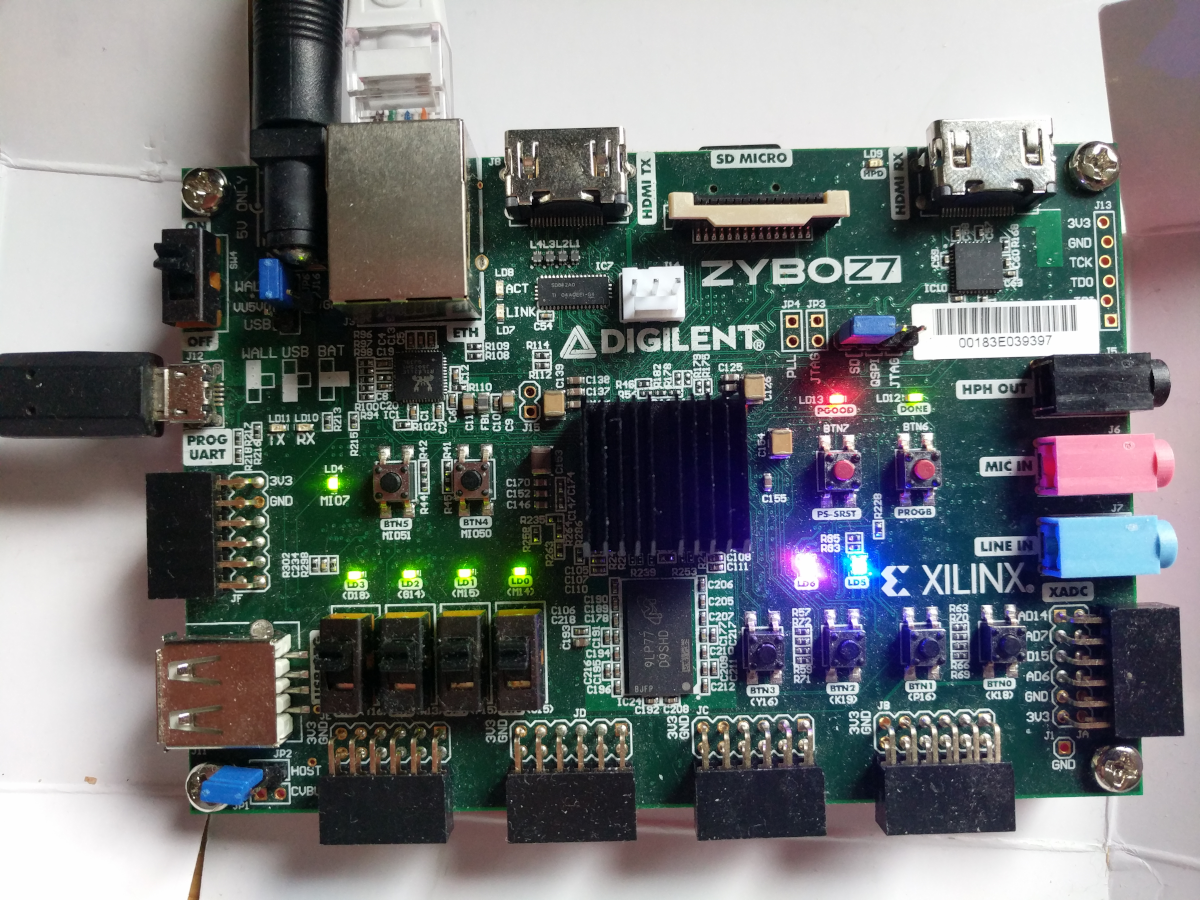
Thus, let’s make use of the shiny hardware! In this article, I am going to use the Zybo Z7 board from Digilent. This board is quite an interesting option for hobbyists as it comes with a lot of on-board peripherals and is still sold for an affordable price. There are two variants, the Z7-10 and the Z7-20, which basically differ in the size of the FPGA (and a few minor details). I have a Zybo Z7-20 at hand, but most aspects of this guide apply to the Z7-10 as well.
|
|
Zybo Z7-20 running the GPIO demo
|
The Z7-20 comes with a bunch of user-controlled LEDs, push buttons and switches. All of which are accessible via the Zynq’s GPIO controller. However, only one LED and two buttons are directly connected to the processing system (PS), the remaining are connected to the PL. In this article I will therefore not only show how to control the Zynq’s GPIO but also how to interact with the PL using GPIO and MMIO. Moreover, as icing on the cake, I am going to switch between different PL-configurations at runtime.
Getting started with the Zybo Z7
As a starting point, let’s first try a known-to-work scenario on the board. First, if you haven’t already done so, obtain a clone of the repository within the main genode repository, prepare the zynq_uboot port and create a build directory:
 genode #> git clone https://github.com/genodelabs/genode-zynq.git repos/zynq
 genode #> ./tool/ports/prepare_port zynq_uboot
 genode #> ./tool/create_builddir arm_v7a
Now, uncomment the zynq repo in build/arm_v7a/etc/build.conf so that it contains this line:
REPOSITORIES += $(GENODE_DIR)/repos/zynq
…and add the following lines to the same file in order to build an SD card image:
  RUN_OPT_zybo  = --include image/uboot
  RUN_OPT_zybo += --include image/zynq_uboot_sdcard
  BOARD_RUN_OPT(zynq_zybo_z7) = $(RUN_OPT_zybo)
With these preparations, you are able to build run/log and prepare the micro SD card for the Zybo board:
 build/arm_v7a #> make run/log BOARD=zynq_zybo_z7 KERNEL=hw
 [...]
 Created SD-card image file var/run/log.img
 build/arm_v7a$ sudo dd if=var/run/log.img of=/dev/mmcblkX bs=1M conv=fsync
Please refer to the previous article in order to enable network booting via TFTP.
Testing the pin driver
Genode 21.11 introduced the Pin I/O session interfaces that have first been implemented by the pin driver for the A64 SoC. Using the A64 pin driver as a blueprint, I followed suit and implemented a pin driver for the Zynq SoC. Thanks to Norman’s slick groundwork, I was able to re-use most of the code and focus on the SoC-specific parts.
With the pin driver at hand, I was already able to control the PS-accessible LED and buttons. Hence, I wrote a tiny test component. The component shall turn the LED on when button 4 was pressed and off when button 5 was pressed. Since I am going to re-use the component later on, it also generates a state report that reflects the LED state.
First, I created the file src/app/zybo_gpio_demo/mio/target.mk.
 TARGET := zybo_gpio_demo_mio
 SRC_CC := main.cc
 LIBS   := base
Second, I added src/app/zybo_gpio_demo/mio/main.cc with the following content:
 /* Genode includes */
 #include <base/component.h>
 #include <irq_session/connection.h>
 #include <pin_state_session/connection.h>
 #include <pin_control_session/connection.h>
 #include <os/reporter.h>

 namespace Demo {

     using namespace Genode;

     struct Main;
 }


 struct Demo::Main
 {
     Env &_env;

     Pin_state::Connection   _btn4 { _env, "Btn4" };
     Pin_state::Connection   _btn5 { _env, "Btn5" };

     Pin_control::Connection _led4 { _env, "Led4" };

     Irq_connection _irq4 { _env, "Btn4" };
     Irq_connection _irq5 { _env, "Btn5" };

     Signal_handler<Main> _irq_handler {
         _env.ep(), *this, &Main::_handle_irq };

     Genode::Expanding_reporter _reporter { _env, "state", "state" };

     void _update_state(bool on)
     {
         _reporter.generate([&] (Genode::Xml_generator & xml) {
             xml.attribute("value", on ? "yes" : "no");
         });

         _led4.state(on);
     }

     void _handle_irq()
     {
         _irq4.ack_irq();
         _irq5.ack_irq();

         if (_btn4.state())
             _update_state(true);
         else if (_btn5.state())
             _update_state(false);
     }

     Main(Env &env) : _env(env)
     {
         _update_state(false);

         _irq4.sigh(_irq_handler);
         _irq5.sigh(_irq_handler);
         _irq4.ack_irq();
         _irq5.ack_irq();
     }
 };


 void Component::construct(Genode::Env &env)
 {
     static Demo::Main main(env);
 }
Note that one needs to instantiate separate Irq_connection objects for each button in addition to the Pin_state::Connection objects.
Last, I created the file run/zybo_gpio_demo.run:
 create_boot_directory

 import_from_depot [depot_user]/src/[base_src] \
                   [depot_user]/src/init \
                   [depot_user]/src/report_rom \
                   [depot_user]/src/zynq_platform_drv \
                   [depot_user]/src/zynq_pin_drv \
                   [depot_user]/raw/[board]-devices

 build { app/zybo_gpio_demo }

 install_config {
     <config>
         <parent-provides>
             <service name="LOG"/>
             <service name="PD"/>
             <service name="CPU"/>
             <service name="ROM"/>
             <service name="IO_MEM"/>
             <service name="IRQ"/>
         </parent-provides>

         <default caps="200"/>

         <start name="report_rom">
             <resource name="RAM" quantum="1M"/>
             <provides>
                 <service name="Report"/>
                 <service name="ROM"/>
             </provides>
             <route>
                 <service name="ROM"> <parent/> </service>
                 <service name="CPU"> <parent/> </service>
                 <service name="PD">  <parent/> </service>
                 <service name="LOG"> <parent/> </service>
             </route>
             <config verbose="yes"/>
         </start>

         <start name="platform_drv" managing_system="yes">
             <binary name="zynq_platform_drv"/>
             <resource name="RAM" quantum="1M"/>
             <provides><service name="Platform"/></provides>
             <config>
                 <policy label="zynq_pin_drv -> ">
                     <device name="gpio0"/>
                 </policy>
             </config>
             <route>
                 <any-service> <parent/> </any-service>
             </route>
         </start>

         <start name="zynq_pin_drv">
             <resource name="RAM" quantum="1M"/>
             <provides>
                 <service name="Pin_state"/>
                 <service name="Pin_control"/>
                 <service name="IRQ"/>
             </provides>
             <route>
                 <service name="ROM"> <parent/> </service>
                 <service name="CPU"> <parent/> </service>
                 <service name="PD">  <parent/> </service>
                 <service name="LOG"> <parent/> </service>
                 <service name="Platform"> <child name="platform_drv"/> </service>
             </route>
             <config>
                 <!-- see below -->
             </config>
         </start>

         <start name="zybo_gpio_demo_mio">
             <resource name="RAM" quantum="1M"/>
             <route>
                 <service name="Pin_control"> <child name="zynq_pin_drv"/> </service>
                 <service name="Pin_state">   <child name="zynq_pin_drv"/> </service>
                 <service name="IRQ">         <child name="zynq_pin_drv"/> </service>
                 <service name="report">      <child name="report_rom"/>   </service>
                 <service name="ROM"> <parent/> </service>
                 <service name="CPU"> <parent/> </service>
                 <service name="PD">  <parent/> </service>
                 <service name="LOG"> <parent/> </service>
             </route>
             <config/>
         </start>

     </config>
 }

 build_boot_image { zybo_gpio_demo_mio }

 run_genode_until forever
Note that I import the zynq_platform_drv and zynq_pin_drv from the depot. The devices ROM is provided by the depot archive raw/zynq_zybo_z7-devices. In the platform driver’s config, I thus only need to specify a policy that gives the zynq_pin_drv component access to the GPIO controller.
Last, let’s fill in the configuration for the zynq_pin_drv. Looking at the Zybo Z7 manual, I identified that LED 4 is connected to MIO pin 7 and that buttons 4 and 5 are connected to MIO pin 50 and 51 respectively. Knowing that GPIO bank 0 covers MIO pins 0 to 31 whereas bank 1 covers pins 32 to 53, we end up with the following configuration for the pin driver:
 <config>
     <in  name="Btn4" bank="1" index="18" irq="rising"/>
     <in  name="Btn5" bank="1" index="19" irq="rising"/>
     <out name="Led4" bank="0" index="7"  default="on"/>

     <policy label_prefix="zybo_gpio_demo_mio -> Btn4" pin="Btn4"/>
     <policy label_prefix="zybo_gpio_demo_mio -> Btn5" pin="Btn5"/>
     <policy label_prefix="zybo_gpio_demo_mio -> Led4" pin="Led4"/>
 </config>
By using irq="rising", the zybo_gpio_demo_mio component is notified of any rising edge on the button pins.
The scenario is built and run as follows:
build/arm_v7a #> make run/zybo_gpio_demo BOARD=zynq_zybo_z7 KERNEL=hw
With this setup, I am able to switch an LED on/off using two push buttons. On the serial console, I could further witness the following output:
 [init -> report_rom] report 'zybo_gpio_demo_mio -> state'
 [init -> report_rom]   <state value="no"/>
 [init -> report_rom] report 'zybo_gpio_demo_mio -> state'
 [init -> report_rom]   <state value="yes"/>
Not spectacular, but still satisfying to see the pin driver at work. In a next step, I created a custom bitstream for the FPGA to control the switches, buttons and LEDs connected to the PL.
Creating a custom bitstream
Implementing a complex custom design for the programmable logic can get fiddly, especially if you are new to the world of FPGAs. My last practice with Xilinx FPGAs was about a decade ago in which the tooling changed quite a bit. I therefore started with a very simple design to check whether I got the basic setup right.
As a prerequisite, I had to install Vivado ML Standard in a separate Ubuntu VM. I was struck by the amount of disk space it took (~60GB) and therefore had to increase the VM size accordingly.
As a starting point, I followed this tutorial. Since it already includes detailed step-by-step instructions for Vivado, I’ll rather stick to a brief summary of the individual steps in this article.
In Vivado, I opened a new project and created a block design using the Flow Navigator on the left side. In the block design, I added the Zynq processing system as an IP (intellectual property) core. After adding an IP core, Vivado usually presents the option to run connection automation to connect all obvious signals. Running the automation connected the DDR and FIXED_IO interfaces of the IP core to the corresponding (automatically created) external ports.
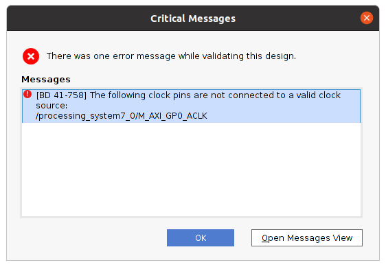
At this point, I was curious whether my bare minimum, yet useless, design was basically complete and correct, and therefore hit the "Validate Design" button.
|
Oops! Apparently, because I skipped adding an AXI IP core as suggested by the aforementioned tutorial, the connection automation was not able to decide on how to connect the AXI clock signal. By locking at the other steps in the tutorial, I was able to decide that the AXI clock signal should be connected to the FCLK_CLK0 interface of the IP core.
Having fixed this, I generated the HDL wrapper (right-click on the block design). Unfortunately, my Vivado installation always got stuck during this procedure as it did when Initializing the Language Server. Changing the syntax checking in Tool -> Settings -> Tool Settings -> Text Editor -> Syntax Checking from "Sigasi" to "Vivado" solved this issue for me after restarting Vivado.
At this point, I started deviating from the aforementioned tutorial. Instead of instantiating an AXI_GPIO IP core (which would require support by the pin driver), I want to interact with the PL using the SoC’s GPIO controller. This is possible because banks 2 and 3 of the GPIO controller are connected to the PL via the EMIO interface. The EMIO signals only need to be routed to the correct pins of the FPGA.
By double-clicking on the Zynq PS IP core, I enabled GPIO EMIO on the Peripheral I/O Pins card. Moreover, on the MIO Configuration card, I set the EMIO GPIO width to 12 (for 4 switches, 4 LEDs, 4 buttons). By doing this, the IP core gained a GPIO_0 interface. In order to make this an external signal, I selected the name and right-clicked to choose Make external from the context menu. This created an external interface named GPIO_0_0 connected to the IP core. Since the GPIO signals are tri-state, the external signal will be named gpio_0_0_tri_io by Vivado. I double-checked this naming scheme by looking into the HDL wrapper (after regenerating it).
Last, I added a Xilinx Design Constraints (XDC) file to tie the gpio_0_0_tri_io signals to those device pins that are actually wired to the switches/LEDs/buttons. Fortunately, Digilent provides master files for their boards. With the master file, one only needs to uncomment individual lines and insert the corresponding signal name. I added the Zybo-Z7-Master file via the Add sources dialogue, uncommented the lines for the LEDs, buttons and switches, and inserted the signal names gpio_0_0_tri_io[0] to gpio_0_0_tri_io[11]. You can find more detailed instructions in the aforementioned tutorial.
When generating the bitstream, I noticed that Vivado eats up a lot of RAM. Since I’m running the tool in a separate Ubuntu VM this caused unexplainable build errors at times. Adding another GB of RAM to the VM and reducing the number of jobs to 1 did the trick for me. Eventually, I was able to export the resulting bitstream file via File -> Export -> Export Bitstream File.
Loading a bitstream at boot-up
Since an FPGA uses volatile memory to store its programming, it must be re-programmed after each power cycle. The bitstream file contains the necessary (device-specific) information. The easiest way is to let the boot loader take care of loading the bitstream. Xilinx’ FSBL as well as u-boot provide support for this. When compiled with the corresponding options, you can load a bitstream using u-boot’s fpga command. There are two sub-commands: load and loadb. The former expects a raw bitstream (.bin) as, e.g., acquired by read-back. The latter expects a .bit file as exported by Vivado. In contrast to the raw bitstream, this file has a different byte order and includes a file header.
In order to simplify the bitstream loading at boot-up, I added two commands to u-boot’s default environment that check for an fpga.bin resp. fpga.bit file and, if present, execute the corresponding fpga command before booting into Genode. Furthermore, you can populate the SD card image with a bitstream by adding the following lines to your etc/build.conf.
RUN_OPT_zybo += --image-uboot-bitstream "/path/to/bitstream.bit"
Testing the bitstream
For a test-drive of the bitstream, I implemented a zybo_gpio_demo_sw component which takes control of the switches and the LEDs that are placed next to each switch. The code is pretty straightforward. You can find it in the genode-zynq repository.
I also added the following start node to the run/zybo_gpio_demo.run script:
 <start name="zybo_gpio_demo_sw">
     <resource name="RAM" quantum="1M"/>
     <route>
         <service name="Pin_control"> <child name="zynq_pin_drv"/> </service>
         <service name="Pin_state">   <child name="zynq_pin_drv"/> </service>
         <service name="IRQ">         <child name="zynq_pin_drv"/> </service>
         <service name="ROM"> <parent/> </service>
         <service name="CPU"> <parent/> </service>
         <service name="PD">  <parent/> </service>
         <service name="LOG"> <parent/> </service>
     </route>
     <config/>
 </start>
Furthermore, and more interestingly, I modified the pin-driver configuration to add the corresponding policies:
 <config>
     <!-- zybo_gpio_demo_mio pins -->
     <in  name="Btn4" bank="1" index="18" irq="rising"/>
     <in  name="Btn5" bank="1" index="19" irq="rising"/>
     <out name="Led4" bank="0" index="7"  default="on"/>

     <policy label="zybo_gpio_demo_mio -> Btn4" pin="Btn4"/>
     <policy label="zybo_gpio_demo_mio -> Btn5" pin="Btn5"/>
     <policy label="zybo_gpio_demo_mio -> Led4" pin="Led4"/>

     <!-- zybo_gpio_demo_sw pins -->
     <in  name="Sw0"  bank="2" index="0" irq="edges"/>
     <in  name="Sw1"  bank="2" index="1" irq="edges"/>
     <in  name="Sw2"  bank="2" index="2" irq="edges"/>
     <in  name="Sw3"  bank="2" index="3" irq="edges"/>
     <out name="Led0" bank="2" index="8"  default="off"/>
     <out name="Led1" bank="2" index="9"  default="off"/>
     <out name="Led2" bank="2" index="10" default="off"/>
     <out name="Led3" bank="2" index="11" default="off"/>

     <policy label="zybo_gpio_demo_sw -> Sw0"  pin="Sw0"/>
     <policy label="zybo_gpio_demo_sw -> Sw1"  pin="Sw1"/>
     <policy label="zybo_gpio_demo_sw -> Sw2"  pin="Sw2"/>
     <policy label="zybo_gpio_demo_sw -> Sw3"  pin="Sw3"/>
     <policy label="zybo_gpio_demo_sw -> Led0" pin="Led0"/>
     <policy label="zybo_gpio_demo_sw -> Led1" pin="Led1"/>
     <policy label="zybo_gpio_demo_sw -> Led2" pin="Led2"/>
     <policy label="zybo_gpio_demo_sw -> Led3" pin="Led3"/>
 </config>
Since I want to trigger an interrupt whenever a switch state changed, I used irq="edges" for the switch input pins.
Implementing a custom IP core
Up to this point, I have neglected the existence of two (one) RGB LEDs on the Zybo Z7-20 (Z7-10). Each of these LEDs is actually composed of three LEDs: a red, a green and a blue one. Every colour can be switched on/off by a distinct pin. Moreover, since the human eye is only able to detect comparably low switching frequencies, we can adjust the brightness by controlling the LEDs' duty cycles. This allows us to basically mix any RGB colour. Although this can be easily done in software, it is a perfect task to be performed by the PL. I therefore implemented a custom IP core that translates an RGB value and a brightness value into the corresponding on/off sequences for each colour.
Still being unfamiliar with Vivado, I found this video and this tutorial a good starting point. A more detailed guide is provided by Xilinx in terms of ug1118.
With this background information, I was able to create my custom IP core via Tool -> Create and Package New IP. In the dialogue, I selected Create a new AXI4 peripheral because I want to implement an MMIO interface. In the final dialogue, I chose Edit IP as a next step.
Vivado’s IP packaging tool already takes care of generating all the boilerplate code. By default, it implements an MMIO interface with four 32bit registers, which is exactly what I needed to control two RGB LEDs.
In order to implement the RGB module, I added a Verilog source file and started implementing a module for driving the pins of a single RGB LED:
 module rgbled(
     output reg [2:0] rgb,
     input wire [6:0] brightness,
     input wire [7:0] red,
     input wire [7:0] green,
     input wire [7:0] blue,
     input wire clk
     );

     // [...] see below

 endmodule
The rgbled module got a three-bit output signal rgb (one bit for each colour). Moreover, it has four input signals for the brightness, red, green and blue values as well as a clock input. If you are new to Verilog and wondering about the difference between reg and wire, I can refer you to this tutorial. In short, a reg signal is able to store some state whereas a wire is merely a connection.
As a first part of the module’s implementation, I added a cycle counter that resets itself to 0 when it hits a certain maximum:
 module rgbled(
     // [...] see above

     reg [14:0] counter;

     wire [14:0] max_cycles;

     always @(posedge clk) begin
         if (counter < max_cycles) begin
             counter <= counter + 1;
         end
         else begin
             counter = 0;
         end
     end

     // [...] see below
 endmodule
Since my module has an 8-bit input for every colour, my idea was to switch each output signal on as long as the counter is smaller than the corresponding colour value. E.g., for a red value of 200, the red LED shall be switched on for 200 cycles. By adjusting the max_cycles value between 255 and "some large value", I can then dim all colours at once. I decided to take brightness values between 0 and 100 in order to scale max_cycles linearly between 255 (brightness 100) and 25500 (brightness 1) with a special case for brightness 0:
 module rgbled(
     // [...] see above

     assign max_cycles =
         brightness > 100 ? 255
                          : (brightness == 0 ? 0
                                             : 255 * 100 / brightness);

     // [...] see below
 endmodule
This made it pretty straightforward to implement the on/off switching logic:
 module rgbled(
     // [...] see above

     always @(posedge clk) begin
         if (max_cycles > 0) begin
             rgb[0] <= red   > counter ? 1 : 0;
             rgb[1] <= blue  > counter ? 1 : 0;
             rgb[2] <= green > counter ? 1 : 0;
         end
         else begin
             rgb <= 3'b000;
         end
     end
 endmodule
This completed the rgbled module, which, however, still needed to be instantiated in the custom IP core. When creating the IP core, Vivado generated two Verilog files. I identified the file suffixed with S00_AXI.v to be the MMIO module and the other file being the top-level module. Looking into the MMIO module, I noticed a comment "Users to add ports here" at the top of the file where I added two lines for the output signals:
 // Users to add ports here
 output wire [2:0] led0,
 output wire [2:0] led1,

 // User ports ends
 // Do not modify the ports beyond this line
At the bottom of the file, I found the comment "Add user logic here" and inserted two instantiations of my rgbled module. Looking at the auto-generated implementation, I spotted that the MMIO registers are named slv_reg0, slv_reg1, slv_reg2 as well as slv_reg3. I thus merely needed to decide on what bits in which register to use for the RGB and brightness values. I ended up with these instantiations:
     // Add user logic here
     rgbled led0_control (
         .clk   (S_AXI_ACLK),
         .red   (slv_reg0[23:16]),
         .blue  (slv_reg0[15:8]),
         .green (slv_reg0[7:0]),
         .brightness (slv_reg1[6:0]),
         .rgb   (led0)
     );

     rgbled led1_control (
         .clk   (S_AXI_ACLK),
         .red   (slv_reg2[23:16]),
         .blue  (slv_reg2[15:8]),
         .green (slv_reg2[7:0]),
         .brightness (slv_reg3[6:0]),
         .rgb   (led1)
     );
     // User logic ends
Since I modified the MMIO module’s ports, I also added two similar output ports to the top-level file and passed them to the MMIO module’s instantiation.
After these changes, I noticed a couple of changes in the Package IP view. First, the File Groups section didn’t have a green tick mark any more. Looking into this section, and following Vivado’s suggestion to merge changes solved this issue. A similar merge wizard was provided in the Ports and Interfaces section. Vivado automatically detected the led0 and led1 ports I added previously. There are no manual adjustments required in this section, yet I learned that I am able to define interfaces of certain types and map ports to these interfaces. One can thereby group signals into a common grouping and assist Vivado’s auto-connection wizardry.
I skipped the interface definition, entered the Review and Package section and packaged my IP core. I got back to my block design and added the newly packaged IP core to the design, ran the auto-connection wizardry and made the led0 and led1 port external (as previously done with the GPIO_0 interface). The address of the MMIO device is automatically assigned by Vivado but can be changed in the Address Editor after opening the block design. Before re-generating the bitstream, I uncommented the lines for the RGB LEDs in the constraints file and inserted the corresponding signal names (led0_0[0] to led0_0[2] and led1_0[0] to led1_0[1]).
Note, if you want to edit an IP core at a later point in time, you can right-click on the core in your block design and select Edit in IP Packager.
Using the custom IP core
With the new bitstream at hand, I implemented a zybo_gpio_demo_rgb component for testing the MMIO interface. This component uses buttons 0 to 3 to cycle through some colours and brightness values of the two RGB LEDs. You can find the code in the genode-zynq repository.
I added the following start node to run/zybo_gpio_demo.run script:
 <start name="zybo_gpio_demo_rgb">
     <resource name="RAM" quantum="2M"/>
     <route>
         <service name="Pin_control"> <child name="zynq_pin_drv"/> </service>
         <service name="Pin_state">   <child name="zynq_pin_drv"/> </service>
         <service name="IRQ">         <child name="zynq_pin_drv"/> </service>
         <service name="Platform">    <child name="platform_drv"/> </service>
         <service name="ROM"> <parent/> </service>
         <service name="CPU"> <parent/> </service>
         <service name="PD">  <parent/> </service>
         <service name="LOG"> <parent/> </service>
     </route>
 </start>
Furthermore, I modified the pin-driver configuration as follows:
 <config>
     <!-- zybo_gpio_demo_mio pins -->
     <in  name="Btn4" bank="1" index="18" irq="rising"/>
     <in  name="Btn5" bank="1" index="19" irq="rising"/>
     <out name="Led4" bank="0" index="7"  default="on"/>

     <policy label="zybo_gpio_demo_mio -> Btn4" pin="Btn4"/>
     <policy label="zybo_gpio_demo_mio -> Btn5" pin="Btn5"/>
     <policy label="zybo_gpio_demo_mio -> Led4" pin="Led4"/>

     <!-- zybo_gpio_demo_sw pins -->
     <in  name="Sw0"  bank="2" index="0" irq="edges"/>
     <in  name="Sw1"  bank="2" index="1" irq="edges"/>
     <in  name="Sw2"  bank="2" index="2" irq="edges"/>
     <in  name="Sw3"  bank="2" index="3" irq="edges"/>
     <out name="Led0" bank="2" index="8"  default="off"/>
     <out name="Led1" bank="2" index="9"  default="off"/>
     <out name="Led2" bank="2" index="10" default="off"/>
     <out name="Led3" bank="2" index="11" default="off"/>

     <policy label="zybo_gpio_demo_sw -> Sw0"  pin="Sw0"/>
     <policy label="zybo_gpio_demo_sw -> Sw1"  pin="Sw1"/>
     <policy label="zybo_gpio_demo_sw -> Sw2"  pin="Sw2"/>
     <policy label="zybo_gpio_demo_sw -> Sw3"  pin="Sw3"/>
     <policy label="zybo_gpio_demo_sw -> Led0" pin="Led0"/>
     <policy label="zybo_gpio_demo_sw -> Led1" pin="Led1"/>
     <policy label="zybo_gpio_demo_sw -> Led2" pin="Led2"/>
     <policy label="zybo_gpio_demo_sw -> Led3" pin="Led3"/>

     <!-- zybo_gpio_demo_rgb pins -->
     <in  name="Btn0" bank="2" index="4" irq="edges"/>
     <in  name="Btn1" bank="2" index="5" irq="edges"/>
     <in  name="Btn2" bank="2" index="6" irq="edges"/>
     <in  name="Btn3" bank="2" index="7" irq="edges"/>
     <policy label_suffix="zybo_gpio_demo_rgb -> Btn0" pin="Btn0"/>
     <policy label_suffix="zybo_gpio_demo_rgb -> Btn1" pin="Btn1"/>
     <policy label_suffix="zybo_gpio_demo_rgb -> Btn2" pin="Btn2"/>
     <policy label_suffix="zybo_gpio_demo_rgb -> Btn3" pin="Btn3"/>
 </config>
For a brief test run, I let the platform driver know about the new MMIO device by (temporarily) adding the following lines to the board/zynq_zybo_z7/devices file:
 <device name="rgbleds" type="my_rgbleds">
     <io_mem address="0x43c00000" size="0x1000"/>;
 </device>
To enable access to this MMIO device, I also added the corresponding policy to the platform-driver configuration:
 <policy label="zybo_gpio_demo_rgb -> ">
     <device name="rgbleds"/>
 </policy>
Note that the zybo_gpio_demo_rgb component will only be functional if the corresponding bitstream is loaded.
Switching bitstreams at run time
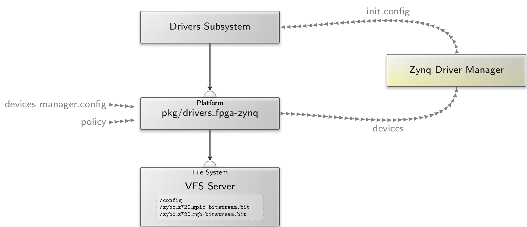
In this section, let’s look into how we can load bitstreams at run time in Genode. The mere reconfiguration of the FPGA is pretty straightforward, yet, it also has its implications on the availability of custom platform devices. To accommodate this use case, I created the depot archive pkg/drivers_fpga-zynq.
|
As illustrated, the pkg/drivers_fpga-zynq subsystem requires two ROM session (devices_manager.config and policy) as well as a File System session. In return, it acts as a platform driver by providing a Platform service. The policy ROM contains the platform-driver configuration, e.g.:
 <report devices="yes"/>
 <policy label_suffix="zynq_pin_driver -> ">
     <device name="gpio0"/>
 </policy>
 <policy label_suffix="zybo_gpio_demo_rgb -> ">
     <device name="rgbleds"/>
 </policy>
The <report> node instructs the internal platform driver to generate a devices report whenever its state changed. This report is used by the Zynq Driver Manager to determine when a certain device became available. In consequence, the Zynq Driver Manager may generate a new init.config to start the corresponding driver component. The driver components and corresponding device dependencies are specified in the manager’s configuration. For starting zybo_gpio_demo_rgb once the my_rgbleds device became available, I am using the following configuration:
 <config>
     <driver name="zybo_gpio_demo_rgb" device="my_rgbleds">
         <binary name="zybo_gpio_demo_rgb"/>
         <resource name="RAM" quantum="2M"/>
     </driver>
 </config>
The devices_manager.config provides the specification of bitstreams and the devices they implement. Instead of adding the rgbleds device to the static devices ROM, as I did in the previous section, we can let the pkg/drivers_fpga-zynq subsystem know about what devices become available by what bitstream. For the two bitstreams I generated previously, I’m using the following devices_manager.config.
 <config>
     <bitstream name="zybo_z720_rgb-bitstream.bit">
         <devices>
             <device name="rgbleds" type="my_rgbleds">
                 <io_mem address="0x43c00000" size="0x1000"/>;
             </device>
         </devices>
     </bitstream>
     <bitstream name="zybo_z720_gpio-bitstream.bit"/>
 </config>
Note that I packaged both ROMs (devices_manager.config and policy) into a raw/zybo_gpio_demo archive.
The pkg/drivers_fpga-zynq subsystem eventually reads the user-provided bitstreams from its File System session. Moreover, the internal fpga_drv component, which is responsible for bitstream loading, gets its configuration from the /config file. This file thus specifies what bitstream shall be loaded into the FPGA, e.g.:
 <config>
     <bitstream name="zybo_z720_rgb-bitstream.bit"/>
 </config>
By simply changing the content of this file, we are able to switch between bitstreams. At this point, it becomes clear why the zybo_gpio_demo_mio component generates a state report. By adding a ROM filter component to the run/zybo_gpio_demo.run script, I can easily realize bitstream switching:
 <start name="rom_filter">
 <resource name="RAM" quantum="1M"/>
 <provides>
     <service name="ROM"/>
 </provides>
 <route>
     <service name="ROM" label="state"> <child name="report_rom"/> </service>
     <service name="ROM"> <parent/> </service>
     <service name="CPU"> <parent/> </service>
     <service name="PD">  <parent/> </service>
     <service name="LOG"> <parent/> </service>
 </route>
 <config>
     <input name="state">
         <attribute name="value"/>
     </input>

     <output node="config">
         <node type="bitstream">
             <if>
                 <has_value input="state" value="yes"/>
                 <then>
                     <attribute name="name" value="zybo_z720_rgb-bitstream.bit"/>
                 </then>
                 <else>
                     <attribute name="name" value="zybo_z720_gpio-bitstream.bit"/>
                 </else>
             </if>
         </node>
     </output>
 </config>
 </start>
Of course, I also need to instantiate all the components shown in the above figure. Let’s start with replacing the platform_drv with the pkg/drivers_fpga-zynq subsystem:
 <start name="platform_drv" caps="1000" managing_system="yes">
     <binary name="init"/>
     <resource name="RAM" quantum="24M"/>
     <provides> <service name="Platform"/> </provides>
     <route>
         <service name="ROM" label="config"> <parent label="drivers.config"/> </service>
         <any-service> <parent/> <any-child/> </any-service>
     </route>
 </start>
Next, I added the Zynq Driver Manager, a subsystem for the dynamic drivers, and a VFS server:
 <start name="zynq_driver_manager">
     <resource name="RAM" quantum="2M"/>
     <route>
         <service name="ROM" label="devices"> <child name="report_rom"/> </service>
         <any-service> <parent/> <any-child/> </any-service>
     </route>
     <config>
         <driver name="zybo_gpio_demo_rgb" device="my_rgbleds">
             <binary name="zybo_gpio_demo_rgb"/>
             <resource name="RAM" quantum="2M"/>
         </driver>
     </config>
 </start>

 <start name="dynamic_drivers" caps="500">
     <binary name="init"/>
     <resource name="RAM" quantum="5M"/>
     <route>
         <service name="ROM" label="config"> <child name="report_rom"/> </service>
         <service name="IRQ"> <child name="zynq_pin_drv"/> </service>
         <any-service> <parent/> <any-child/> </any-service>
     </route>
 </start>

 <start name="vfs">
     <resource name="RAM" quantum="8M"/>
     <provides><service name="File_system"/></provides>
     <route>
         <service name="ROM" label="fpga.config"> <child name="rom_filter"/> </service>
         <any-service> <parent/> </any-service>
     </route>
     <config>
         <vfs>
             <rom name="config" label="fpga.config"/>
             <rom name="zybo_z720_gpio-bitstream.bit"/>
             <rom name="zybo_z720_rgb-bitstream.bit"/>
         </vfs>
         <default-policy root="/" writeable="no"/>
     </config>
 </start>
Last, I updated the import_from_depot line as follows:
 import_from_depot [depot_user]/src/[base_src] \
                   [depot_user]/src/init \
                   [depot_user]/pkg/drivers_fpga-zynq \
                   [depot_user]/src/driver_manager-zynq \
                   [depot_user]/src/report_rom \
                   [depot_user]/src/rom_filter \
                   [depot_user]/src/vfs \
                   [depot_user]/raw/zybo_gpio_demo \
                   [depot_user]/src/zynq_pin_drv \
                   [depot_user]/raw/[board]-devices
Giving the modified run script a spin, I got this output:
 build/arm_v7a #> make run/zybo_gpio_demo BOARD=zynq_zybo_z7 KERNEL=hw
 ...
 [init -> report_rom] Warning: no policy defined for label 'zynq_driver_manager -> devices'
 [init -> report_rom] Warning: no valid policy for ROM request 'zynq_driver_manager -> devices'
 [init -> report_rom] Warning: no policy defined for label 'dynamic_drivers -> config'
 [init -> report_rom] Warning: no valid policy for ROM request 'dynamic_drivers -> config'
 [init -> report_rom] Warning: no policy defined for label 'rom_filter -> state'
 [init -> report_rom] Warning: no valid policy for ROM request 'rom_filter -> state'
 ...
Of course, I forgot adding the policy definitions to the report_rom configuration, hence I added a policy node for each of the logged labels:
 <config verbose="no">
     <policy label="rom_filter -> state"
               report="zybo_gpio_demo_mio -> state"/>
     <policy report="platform_drv -> platform_drv -> devices"
               label="zynq_driver_manager -> devices"/>
     <policy report="zynq_driver_manager -> init.config"
               label="dynamic_drivers -> config"/>
 </config>
Another spin on the run script produced the following output:
 [init -> vfs] Error: ROM-session creation failed (ram_quota=6144, cap_quota=3, label="zybo_z720_gpio-bitstream.bit")
 [init -> vfs] Error: Could not open ROM session for "zybo_z720_gpio-bitstream.bit"
 [init -> vfs] Error: failed to create <rom> VFS node
 [init -> vfs] Error:    name="zybo_z720_gpio-bitstream.bit"
 [init -> vfs] Error: ROM-session creation failed (ram_quota=6144, cap_quota=3, label="zybo_z720_rgb-bitstream.bit")
 [init -> vfs] Error: Could not open ROM session for "zybo_z720_rgb-bitstream.bit"
 [init -> vfs] Error: failed to create <rom> VFS node
 [init -> vfs] Error:    name="zybo_z720_rgb-bitstream.bit"
I have not provided the bitstream files yet. For a brief test, I could simply copy the files into build/arm_v7a/bin and add them to the build_boot_image line. However, I had another solution in mind that makes use of Goa.
Building and packaging bitstreams for Genode
In order to provide bitstreams in form of depot archives, I added Vivado support to Goa. Fortunately, Vivado provides a command to export a project in form of a tcl script, which allows re-creation of the project. In this section, I will focus on how to use Goa's Vivado support.
First, I need to export the Vivado project I want to package. Thus, in the Vivado’s TCL console, I enter the following command:
write_project_tcl -paths_relative_to /home/johannes/vivado_workspace /tmp/vivado.tcl
The -paths_relative_to argument is essential because it converts the paths of the source files into relative paths. In my goa-projects repository, I created the subdirectory zynq/zybo_z720_rgb-bitstream/ to create a new Goa project and copy vivado.tcl into the src/ subdirectory of the new Goa project. By inspecting the tcl file, we can get a list of required source files. In my tcl file, the following lines catch my attention:
 proc checkRequiredFiles { origin_dir} {
   set status true
   set files [list \
  "[file normalize "$origin_dir/xilinx/project_2/project_2.srcs/constrs_1/imports/Downloads/Zybo-Z7-Master.xdc"]"\
   ]
   foreach ifile $files {
     if { ![file isfile $ifile] } {
       puts " Could not find local file $ifile "
       set status false
     }
   }

   set paths [list \
  "[file normalize "$origin_dir/../../[file normalize "$origin_dir/xilinx/ip_repo/rgbled_1.0"]"]"\
   ]
   foreach ipath $paths {
     if { ![file isdirectory $ipath] } {
       puts " Could not access $ipath "
       set status false
     }
   }

   return $status
 }
The checkRequiredFiles procedure provides a first hint regarding what source files I have to copy into my Goa project. In this case, it lists the constraints file as well a the path of my custom IP core.
Note that Goa will mirror all files from the src/ directory to the archive’s build directory. Furthermore, it will use the build directory as $origin_dir when re-creating the Vivado project. The required files must therefore be copied into the src/ directory with their corresponding relative paths.
By adding an artifacts file to my Goa project, I further tell Goa what build artifact(s) to include into the bin/<arch>/zybo_z720_rgb-bitstream archive. Since Goa writes the bitstream to a file named after the pattern <project_name>.bit, the artifacts file must have the following content:
zybo_z720_rgb-bitstream.bit
Moreover, as a bin archive is always tied to a particular CPU architecture, I set the target architecture to arm_v7a by adding a .goarc with the following content:
 set arch arm_v7a
 set jobs 1
Note that I also restrict the number of jobs to 1 to reduce Vivado’s resource consumption. With these requisites, goa build produces the following error:
Error: tool-chain prefix is not defined
This message hints at the fact that there is no built-in support for arm_v7a in Goa yet. I therefore define the tool-chain prefix manually by adding the following line to the .goarc file:
set cross_dev_prefix "/usr/local/genode/tool/current/bin/genode-arm-"
Now, goa build complains about a missing vivado binary:
 Error: build-directory creation via vivado failed:
  couldn't execute "vivado": no such file or directory
Of course, I forgot to source the Vivado environment. After fixing this as follows, Goa is able to build the bitstream within a couple of minutes:
 zybo_z720_rgb-bitstream #> source /tools/Xilinx/Vivado/2021.1/settings64.sh
 zybo_z720_rgb-bitstream #> goa build
 ...
 [zybo_z720_rgb-bitstream:vivado] 10 Infos, 0 Warnings, 0 Critical Warnings and 0 Errors encountered.
 [zybo_z720_rgb-bitstream:vivado] write_bitstream completed successfully
 [zybo_z720_rgb-bitstream:vivado] write_bitstream: Time (s): cpu = 00:00:11 ; elapsed = 00:00:13 . Memory (MB): peak = 3202.781 ; gain = 451.625 ; free physical = 1133 ; free virtual = 2434
 [zybo_z720_rgb-bitstream:vivado] INFO: [Common 17-206] Exiting Vivado at Thu Oct  6 15:35:31 2022...
With the successful build, I am ready to try goa export --depot-user jschlatow. The output reminds me to add a LICENSE and a version file. After adding these files, I am ready to export and publish the depot archive.
Using the packaged bitstreams
After I published the bitstream archives for the demo from my Vivado-enabled Ubuntu VM, I was able to download them on my Archlinux VM that I use for Genode development:
 genode #> ./tool/depot/download jschlatow/bin/arm_v7a/zybo_z720_rgb-bitstream/2022-09-29
 genode #> ./tool/depot/download jschlatow/bin/arm_v7a/zybo_z720_gpio-bitstream/2022-09-27
The very last missing piece of the puzzle was then to add the following arguments to the import_from_depot procedure in run/zybo_gpio_demo.run.
 import_from_depot ...
                   jschlatow/src/zybo_z720_rgb-bitstream/2022-09-29 \
                   jschlatow/src/zybo_z720_gpio-bitstream/2022-09-27 \
                   ...
Now, when running make run/zybo_gpio_demo, I can use buttons 4 and 5 to switch between the two bitstreams.
For reproducing the demo, you can find the complete run script and source files in the genode-zynq repository.
Edit 2022-11-01: Updated links to genode-zynq repository (staging -> master).
Edit 2023-05-08: Updated link to goa repository (moved to genodelabs).